Project overview
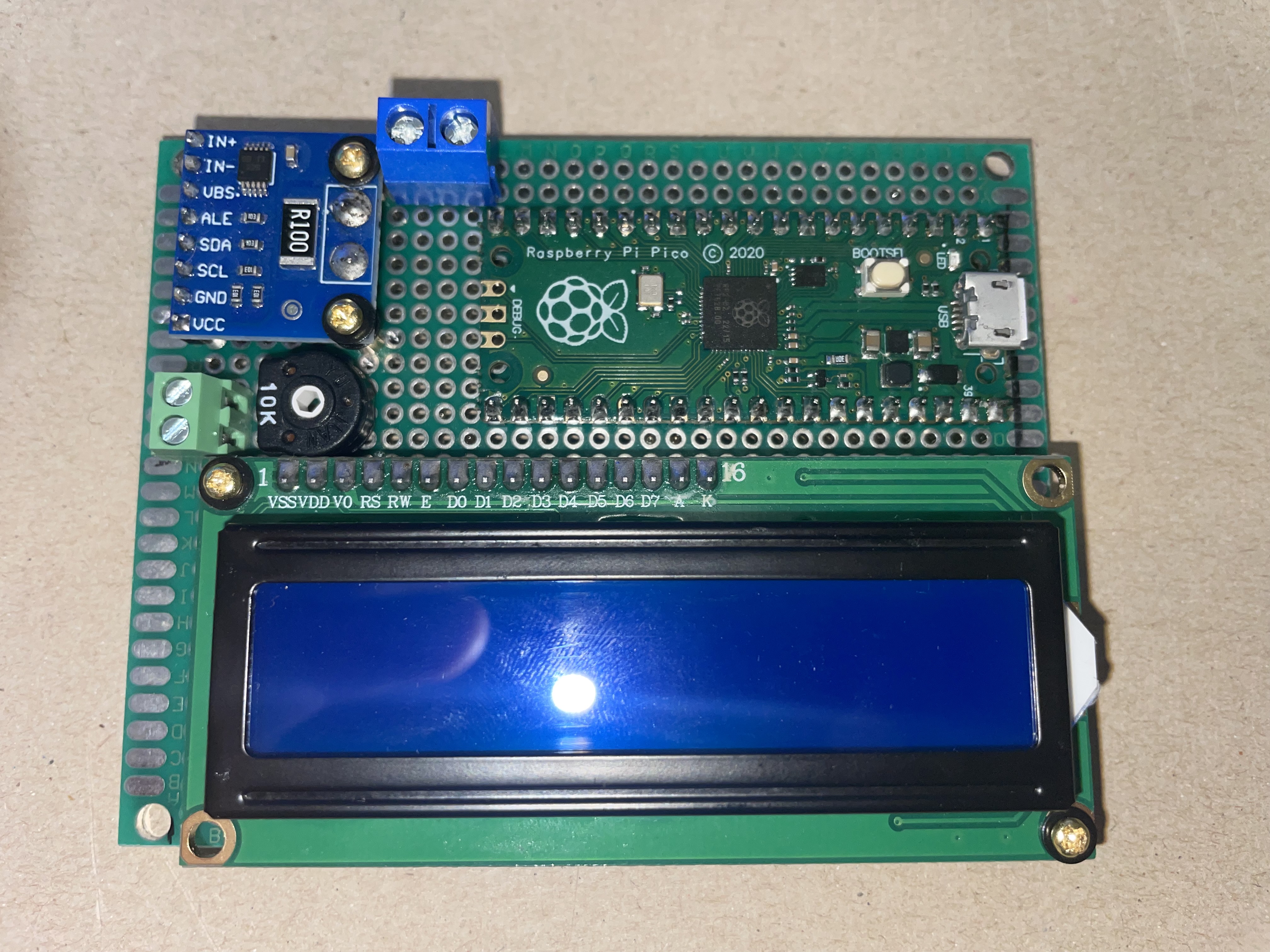
Figure 1: RPi Pico, LCD and INA226-Module soldered onto 70 cm x 90 cm
breadboard
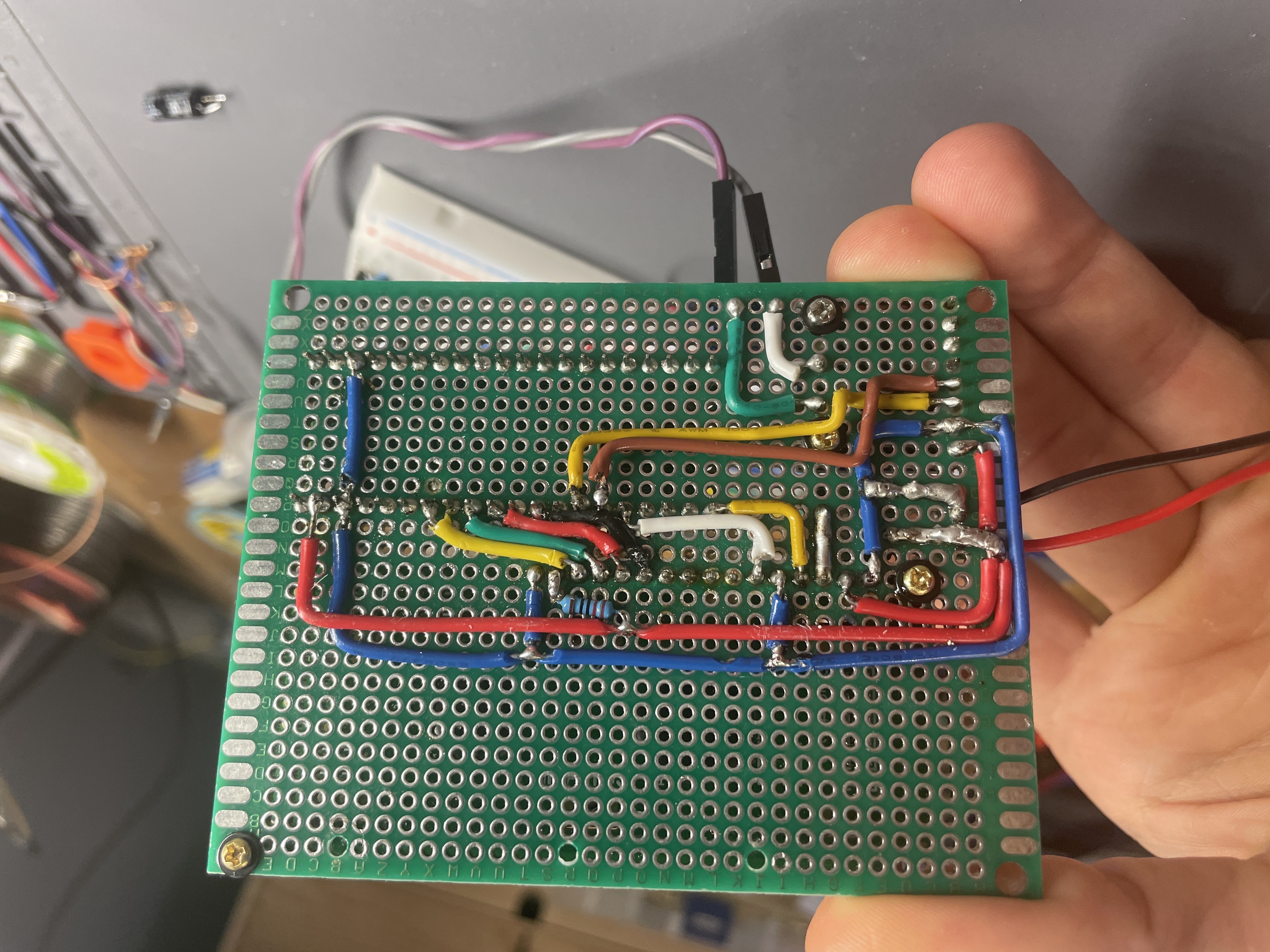
Figure 2: The wiring on the bottom of the breadboard
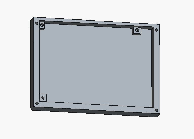
Figure 3: Lower part of the housing for the current monitor in FreeCAD
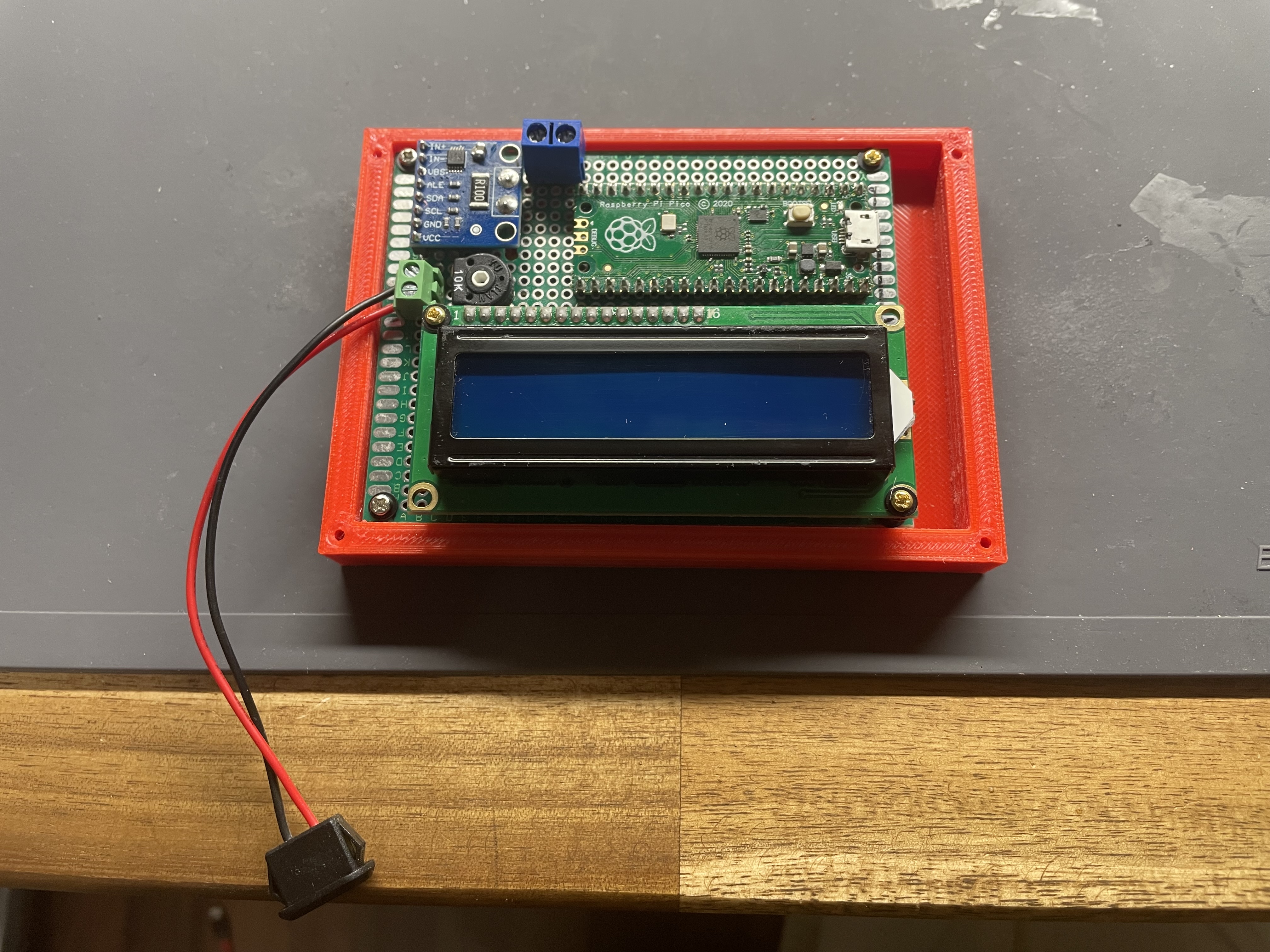
Figure 4: Breadboard screwed into the bottom part of the housing.
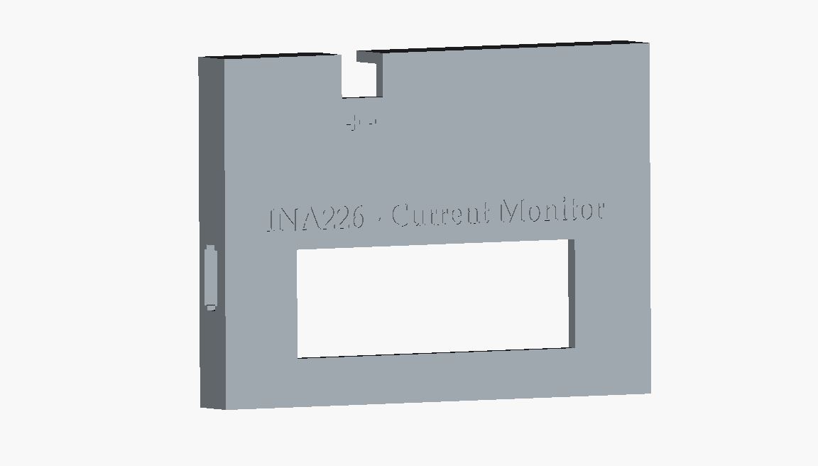
Figure 5: Upper part of the housing for the current monitor in FreeCAD.
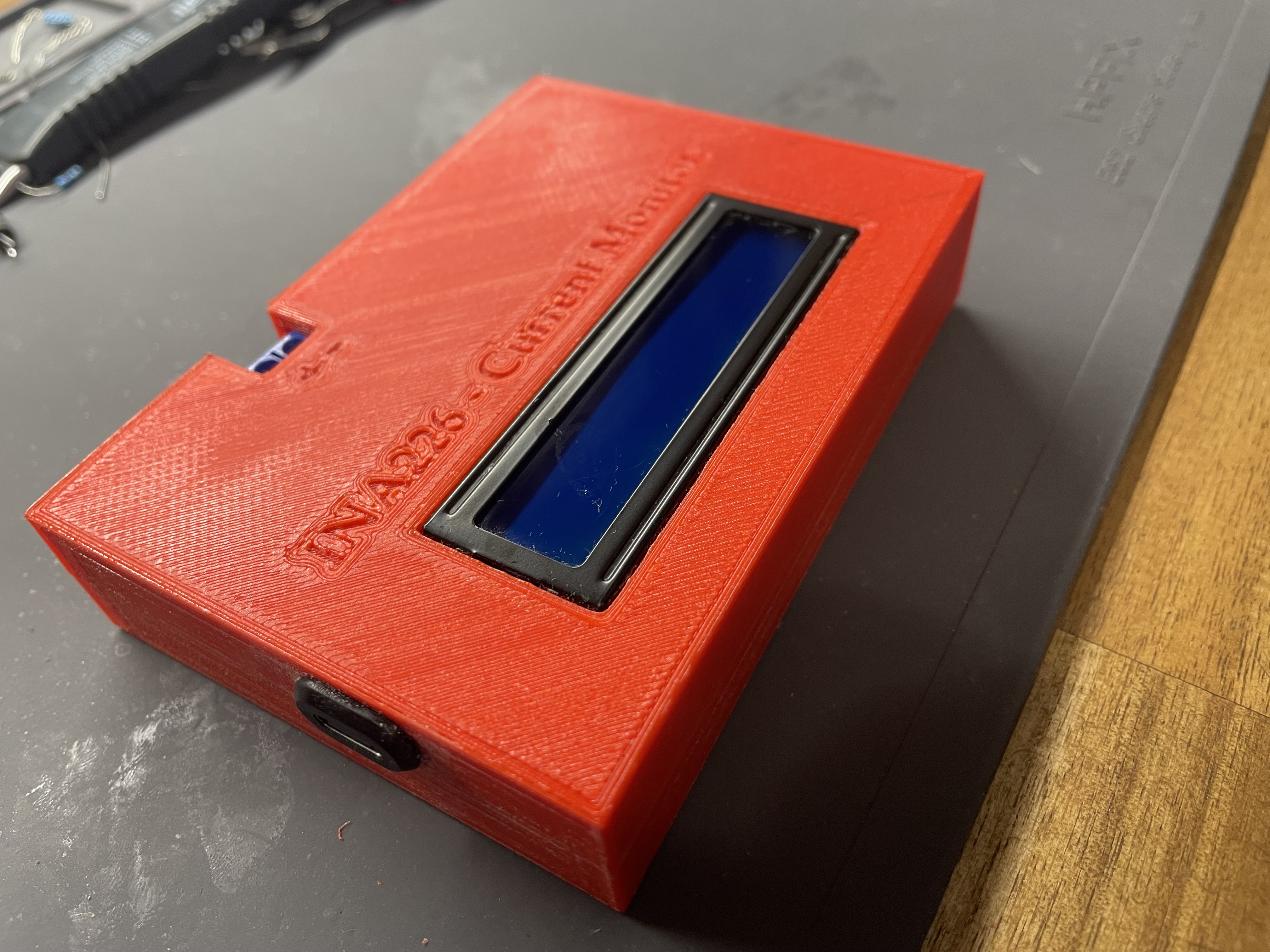
Figure 4: the final current monitor screwed together
Housing - Current Monitor
Breadboard
To be able to make it portable, I needed to solder the Raspberry Pi as well as the LCD and the INA226 module onto a breadboard.
3d printed housing
So, since I wanted the device to look like a device, not like test setup, I decided to design a simple housing.
First I designed the bottom part and 3d printed it.
Then I checked, if the breadboard fits inside. Also if the screw holes are aligned correctly.
I then designed the top part and printed it as well. Here I needed two runs, because I needed to fix the height.