Test Setup - Current Monitor
Bill of Materials
| Item | Quantity | Description | Notes |
|---|---|---|---|
| Raspberry Pi Pico | 1 | Microcontroller Board | Main controller |
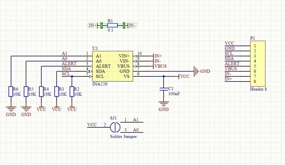
| INA226-Board | 1 | INA226 Current monitor module | Measuring the current |
| LCD Display | 1 | 1602 LCD module display 2x16 | Display that shows the measured current |
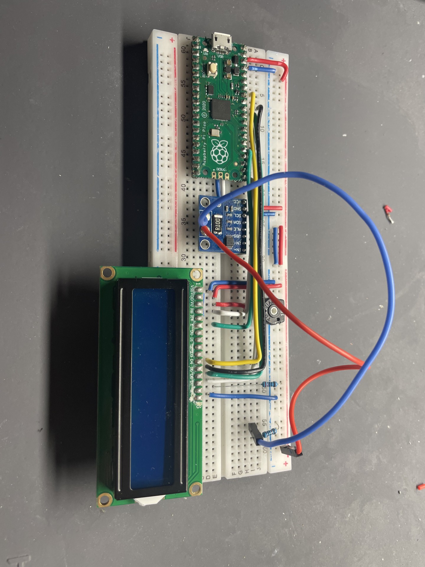
| Breadboard | 1 | Prototyping board | For wiring |
| 10k potentiometer | 1 | Adjustable 10k potentiometer | To adjust the brightness with the VO-Pin on the LCD |
| Wires | - | Solid copper wires | Connecting the boards |
Wiring
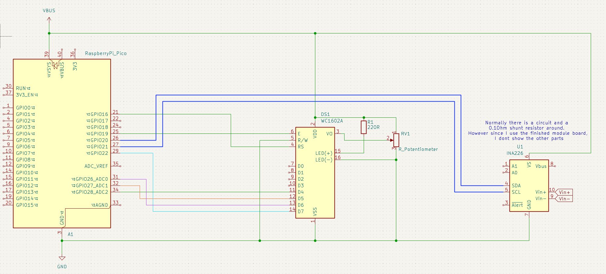
For the wiring of the LCD I have used the 4-bit mode, like it is explained on the LCD Arduino Library page.
I have configured the I2C0 Pins GP20(SDA) and GP21(SCL) on the RPI Pico to communicate with the INA226. Just to mention, the INA226 can also measure a voltage on the VBUS pin, which I don´t use. However it can be changed, if needed, later on. The 10k potentiometer adjusts the brightness/contrast of the display. I just looked for the resistance where the text was the clearest.
Programming
I have programmed the RPI Pico through the Arduino IDE. The only thing to adjust, is to set the board setting on "Raspberry Pi Pico".
#include <Wire.h>
#include <LiquidCrystal.h>

#define INA_ADDR_1 0x40

// rs, enable, d4, d5, d6, d7
LiquidCrystal lcd(16, 19, 28, 27, 26, 22);

// I2C-Pins anpassen
const int PIN_SDA = 20;   // <- deine Pins
const int PIN_SCL = 21;


void write16(uint8_t ina_addr, uint8_t reg, uint16_t val){
  Wire.beginTransmission(ina_addr);
  Wire.write(reg);
  Wire.write(val >> 8);
  Wire.write(val & 0xFF);
  Wire.endTransmission();
}

int16_t read16s(uint8_t ina_addr,uint8_t reg){
  Wire.beginTransmission(ina_addr);
  Wire.write(reg);
  Wire.endTransmission(false);
  Wire.requestFrom(ina_addr, (uint8_t)2);
  return (int16_t)((Wire.read()<<8)|Wire.read());
}


void setup(){

  Wire.setSDA(PIN_SDA); Wire.setSCL(PIN_SCL);
  Wire.begin();

  // --- AVG=128, t=1.1ms, MODE=continuous ---
  write16(INA_ADDR_1,0x00, 0x0927);


  //--- Calibration for Rshunt=0.1 Ω (Current_LSB=10 µA/bit) max current 0.33 A---
  write16(INA_ADDR_1,0x05, 0x1400);   // CAL=5120

  lcd.begin(16,2);

}


double I_acc_mAs = 0.0f;
double I_acc_mAh = 0.0f;

unsigned long lastSecondTime = 0;
unsigned long lastUpdateTime = 0;
unsigned long seconds = 0;
unsigned long minutes = 0;
unsigned long hours = 0;


void loop(){
  unsigned long now = millis();

  if (now - lastSecondTime >= 1000) {
    lastSecondTime = now;
    seconds++;
    if(seconds > 59)
    {
      seconds = 0;
      minutes++;
    }
    if(minutes > 59){
      minutes = 0;
      hours++;
    }
  }


  //Offset quick fix shunt register
  int8_t shunt_off_raw_1 = -9;
  //Offset quick fix current register
  int8_t shunt_off_raw_2 = -22;
  float corr_val = 1.19; //correction factor

  // raw value
  int16_t shunt_raw_1 = read16s(INA_ADDR_1,0x01) - shunt_off_raw_1 ;// SHUNT VOLTAGE

  float Ushunt_mV_1 = shunt_raw_1 * 2.5e-3;       // 2,5 µV/LSB -> mV
  Ushunt_mV_1 =  Ushunt_mV_1 * corr_val;
  float I_mA_UR_1   = Ushunt_mV_1 / 0.1f;         // Rshunt=0.1 Ω

  int16_t cur_raw_1 = read16s(INA_ADDR_1,0x04) - shunt_off_raw_2 ; // CURRENT (needs CAL)
  float I_mA_reg_1  = cur_raw_1 * 0.01f;         // 10 µA/Bit
  I_mA_reg_1 = I_mA_reg_1 * corr_val;

  I_acc_mAs = I_acc_mAs + I_mA_reg_1 * 0.5f;  //accumulate the current every 0.5 seconds


  lcd.clear();
  lcd.setCursor(0, 0);

  lcd.print("I: ");
  lcd.print(I_mA_reg_1,3);
  lcd.print("mA");

  // update only every 10 seconds ---
  if (now - lastUpdateTime >= 10000) {  // 10 000 ms = 10 s
    lastUpdateTime = now;
    I_acc_mAh = I_acc_mAs / 3600.0;

  }


  lcd.setCursor(0, 1);
  if(I_acc_mAh < 100) lcd.print(I_acc_mAh ,3);
  else lcd.print(I_acc_mAh ,2);
  lcd.print("mAh ");


  if(hours < 10)lcd.print("0");
  lcd.print(hours);
  lcd.print(":");

  if(minutes < 10)lcd.print("0");
  lcd.print(minutes);

  delay(500);
}
INA226 Functionality
The maximum voltage, which the INA226 can measure is 81.92 mV. The LSB is 2.5 uV(25 uA with 0.1 Ohm). With a resistor of 0.1 Ohm it means that the maximum measurable current is 0.8192 Amps. Currents above that will saturate and result in clipping internally.
However, there is a Current Register (0x04h), which can be calibrated. We can adjust the LSB on that by writing in the Calibration Register (0x05h). I chose to configure an LSB of 10 uA. The calibration value for that is calculated as follows:
CAL = 0.00512 / (Current_LSB x R_Shunt) = 0.00512 / (10 uA x 0.1 Ohm) =
      5120
Using the LSB of 10 uA has the downside that the maximum current the Current Register can show is
Current_LSB = Maximum Current/2^15
--> Maximum Current = 0.327 A
To be honest, it doesnt really make the difference if it is 10 uA or 25 uA, I just left it at 10 uA.
Precision and Noise
Layout and configuration
TI says in the
datasheet,
that for noisy circuits a filter on the input pins can be used. Since I
have bought an already finished layout and didn´t want to make my life too
hard, I decided to configure an averaging of 128 with a conversion time of
1.1 ms (continuous) at least to filter out a little bit of noise. The
configuration register address is 0x00h. You can see that in my
setup() function.
About the precison
So, in electronics there is always some type of tolerance or error. With sensors the manufacturer for instance tells which tolerance at what measurement and what temperature it has. Good sensors are calibrated. But...whenever YOU use them in most cases you also have to calibrate, because theirs somehow doesn´t work, because they had an ideal test environment which is usually not the case when it´s used in the "real world".
However after measuring some currents with different resistors I came to the conclusion that these module boards are even worse. One reason is that the layout is not really good for measuring currents (No Kelvin-4-Wire-Connection). Also when you buy these boards, you don´t get a datasheet for every used piece as well as the shunt resistor, so you don´t know how precise the 100 mOhm (in my case) resistor is.
Since we cant change that, what can normally be done is to calibrate the measured current in the firmware. It can be done by using a precise Ampere meter or a constant current supply. Something where you can say "THAT" used actually be the measured current.
Yeah....I don´t have any of these precise devices, especially for low currents...But what I do have, is 2 different resistors witch a tolerance of 0.1% 😎 One is 5.1 kOhms and the other is 316 Ohms.
So I am using my power supply to supply a voltage of 5 V on each of these resistors:
I = 5 V / 316 Ohm(± 316 mOhm) --> I+ = 15.8069 mA | I- = 15.8386
        mA
I = 5 V / 5100 Ohm(± 5.1 kOhm) --> I+ = 0.9794 mA | I- = 0.9813
        mA mA
Just to showcase, that .1% of a tolerance is good in MY case for my application but not good enough, if it should be ACTUALLY precise.
To make it short, I assumed that they are ideal resistors and what current should be drawn. Then I used my INA226 with the offset correction values at open circuit state ( =0 mA), but no correction factor YET to read the measured current.
The ratio r = I_ideal / I_measured of both values for both
resistors was around 1.19 (again, I assume that the deviation is constant,
because of my lack of data). That means my measured current with the
module was almost 20% lower then what it should be. I blame the shunt
resistor...Because there is no way that, without calibration, it is off by
a FIFTH...right ?? 😅
However that is the value
float corr_val = 1.19;
in the programm above.
Now I get a current of
I(316R) = 15.872 mA (r = 0.996 tolerance = -0.31%) and
I(5k1R) = 0,976 mA (r = 1.0045 tolerance = +0.45%)
Maybe sometime later I will do a better calibration, but for now that is enough for me.
Reading and Calculation
To read out the raw value/s, we take a look at the registers 0x01(Shunt Voltage) and 0x04 (Current), starting off with the first one.
We read out the raw value, multiply it to the LSB of 2.5 uV and divide it by 0.1 Ohm to get the current.
Current_mA(0x01h) = raw * 2.5 mV / 0.1 Ohm
Since the current register already stores in amps, we just read the raw value from the 0x04(Current Register) and multiply it to the value we calibrated. In our case it was 10uA or 0.01 mA
Current_mA(0x04h) = raw * 0.01 mA
Lastly I have decided to update the LCD every 500 ms and the accumulated charge every 10 seconds. Thats generally it.
Note
Don´t use these typical jumper cables to sense the current, because they don´t have a good conductivity and can deflect the measured current pretty noticably. These solid copper wires are better.