Assembly + Tests
3D-Model
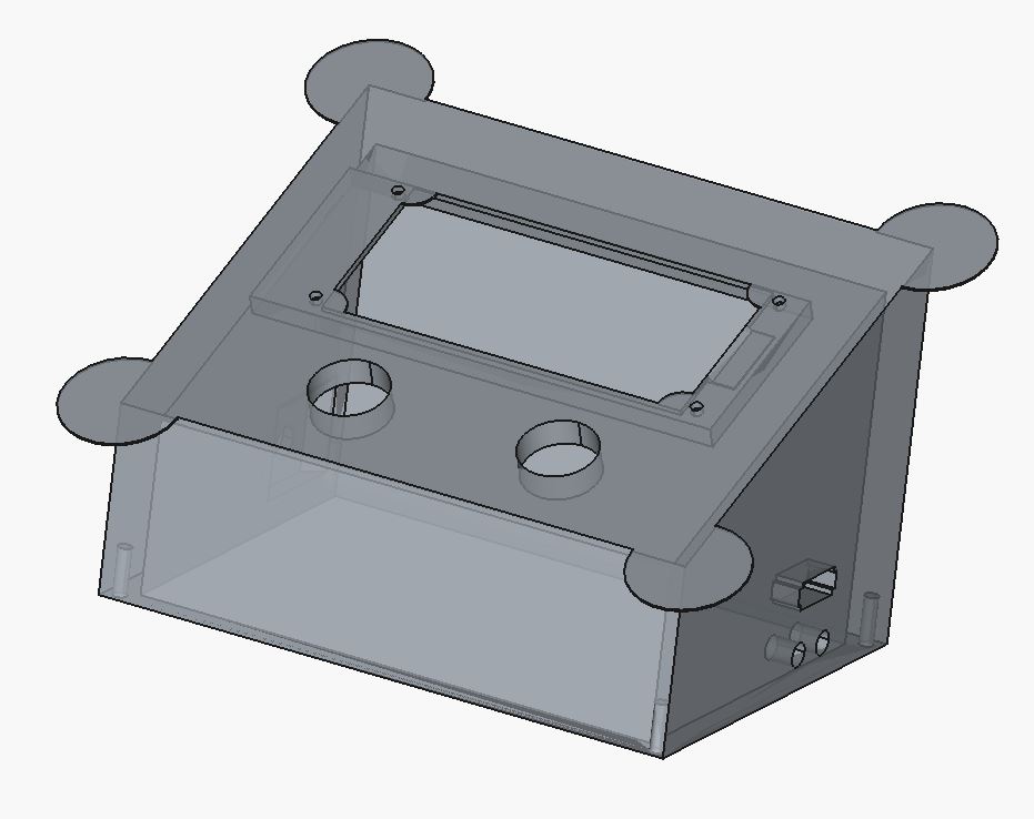
Top Part
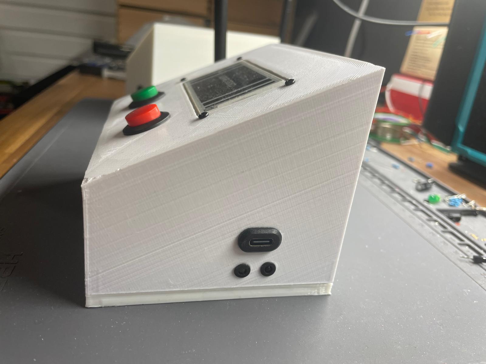
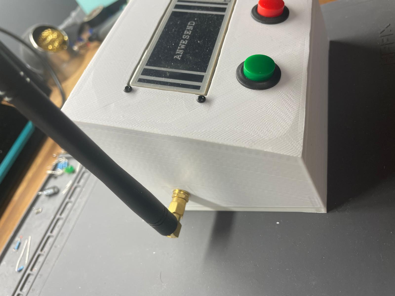
The main idea is to let the sender sit on a desk. So I thought of a slope on the top, where the display is placed. The buttons, which will signal the receiver will be mounted on the slope as well, below the display. This can be seen on figure 1.
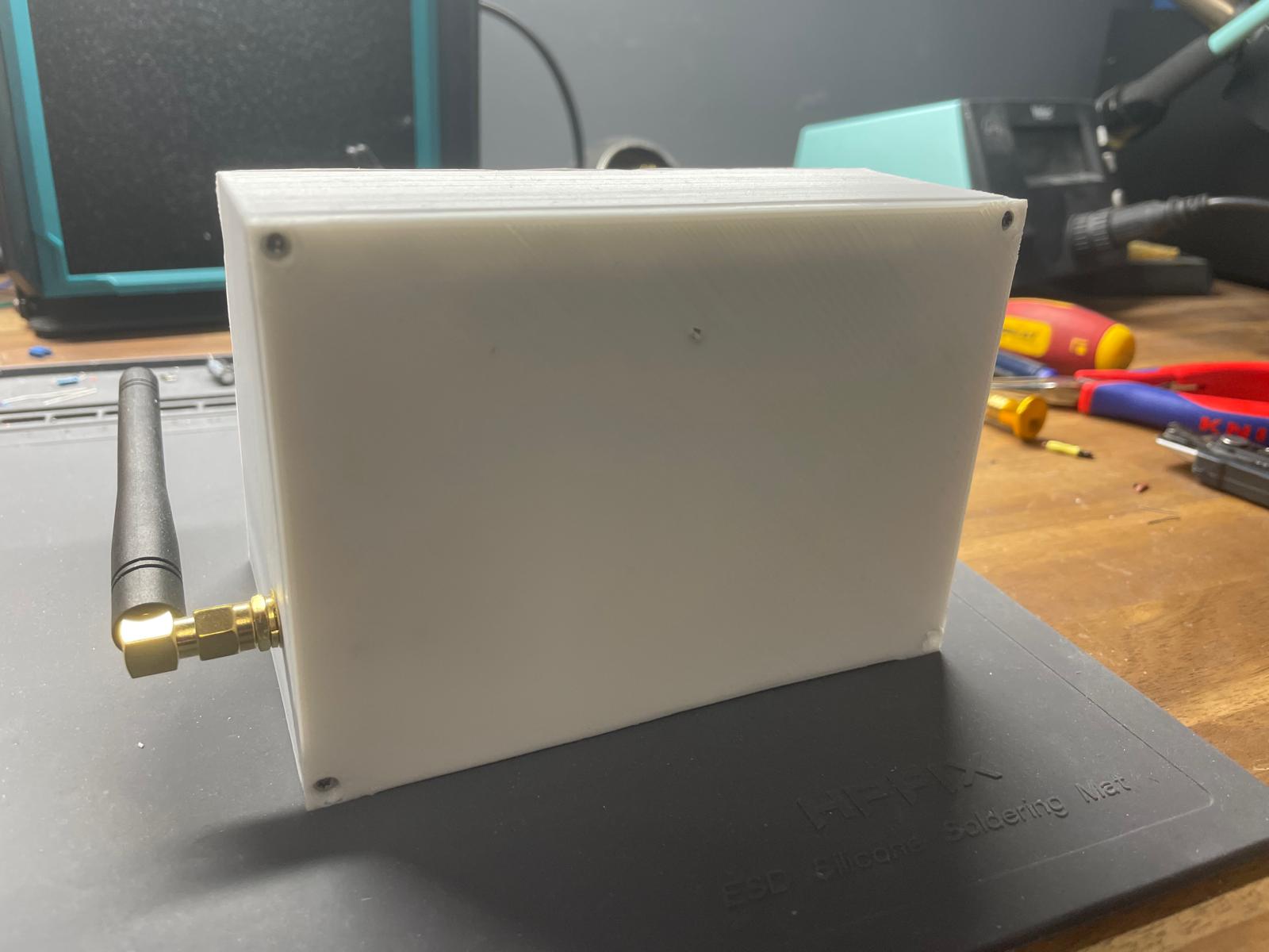
On the side there are 2 small holes which are meant for the yellow LED, which signals "Charging"-state and a red LED to signal a low battery state as discussed. On top of them, there is a bigger rectangular hole, where the USB-C port will be mounted in. On the other side is a hole to be able to mount the antenna onto it.
Bottom Part
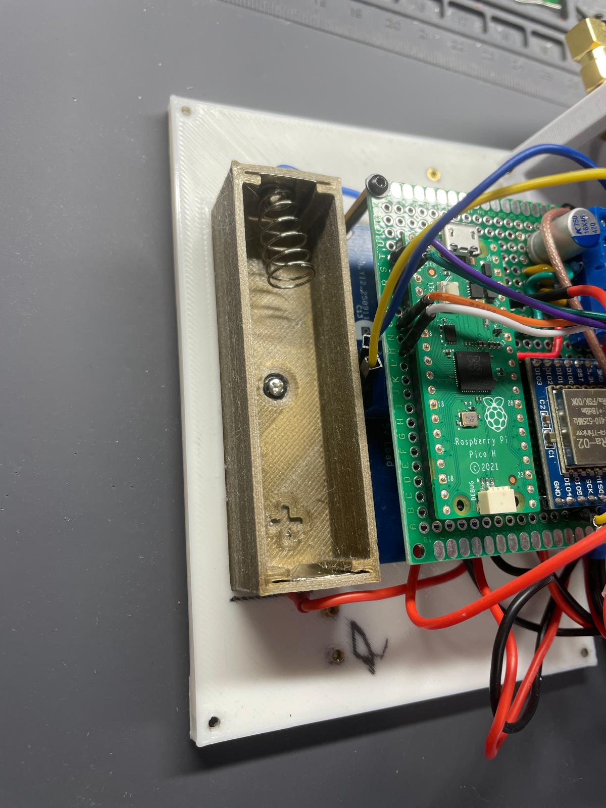
The bottom part will be mounted to receptables through 4 holes, which are mounted into the corners of the top part. The rest is pretty simple, there is a pocket for the battery holder and four elevation plateaus to give the bottom of the first board some space. The last could also be done through some screwable spacers, but with that I safed 4 of them. Figure 3 shows the printed bottom part with the battery holder and boards screwed onto it.
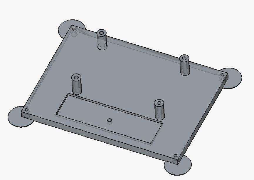
for printing stability, a pocket for the battery holder and a plateau for the boards.
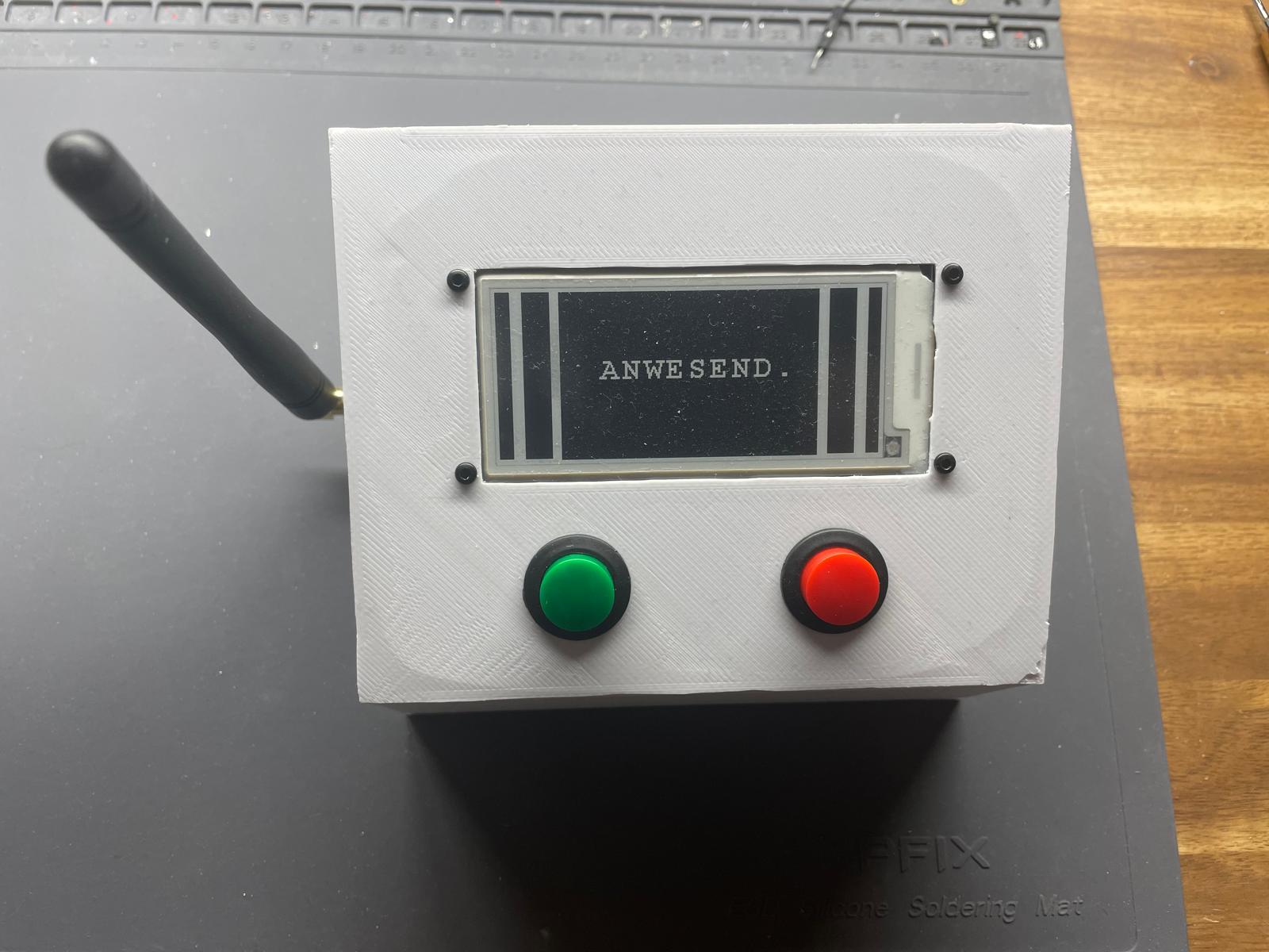
This is how the sender looks. I know the print is not that pretty, but that´s another topic.
Changes in code for efficiency and stability
Before I show you the tests I want present the whole code for the sender and receiver. One reason is because I want to present the whole finished code alltogether. The other reason is because I have changed some things up to make it cleaner and optimized. I will explain in the following, what I mean by that.
Encryption
I am not an expert on encryption, but I have done a little bit of research on how to encrypt messages safely. For example, since I always send the same strings, with the previous encryption, the encrypted message would always be the same. This would lead to hackers eventually figuring the key out over time.
Instead you could use a so called nonce counter which is a simple number, that counts up with every message. With that even the same encrypted message will always differ because before encryption the nonce number gets added to the message. Another thing I changed, is the message itself. It is a waste of payload to send strings like "LED ON" or "LED OFF" to signal 2 different states. Might as well send 1 or 0, which is only one bit. Before the payload was 16 bytes but unsafe, now the payload consists of 17 bytes but safely encrypted with a tag:
[ nonce (8) ][ cipher (1) ][ tag (8) ]
The 17 bytes consist of 8 byte for the nonce counter, 1 byte ciphered message and 8 byte for the tag, which validates the message by comparing to the key. For sending and receiving, there are different keys and nonce counters. Both keys have to be known by both devices. Even better would be to use some type of crypto chip (hardware)...
EU Rules for LoRa
In EU(where I live) there are 2 simple rules for 433 MHz, because this frequency is widely used and free to use. First the sending power mustn´t exceed 10dbm, secondly the sending duration must not exceed 6s/per minute or generally max 10% duty cycle. In addition, immediately after sending ONE time the sender now waits a second for a response, whereas in the previous code it sent 18 times in a loop and then waited for a response. That makes it a lot more effizient and clean because in the previous setup it still sends even after reaching the receiver after one iteration. There are other factors to strengthen the signal and the probability of the signal being received like the spreading factor, bandwith and preamble length. This is the setup I have used:
Payload (PL)     = 17 byte
SF               = 8
Bandwidth (BW)   = 125 kHz
Coding Rate      = 4/5
Preamble         = 64 symbols
CRC              = an
1) symbol length
Tsym = 2^SF / BW
     = 256 / 125000
     = 2,048 ms
2) preamble length
Tpreamble = (64 + 4,25) · 2,048 ms
          ≈ 139,8 ms
3) payload-symbols
payloadSymbNb = 33 symbols
4) Payload-Time
Tpayload = 33 · 2,048 ms
         ≈ 67,6 ms
5) full length
ToA = 139,8 ms + 67,6 ms
    ≈ 207 ms
This means that one message with my configuration takes around 207 ms to send, where 140 ms of that time is only the preamble. The preamble, which I have made so long because the receiver wakes up only once every second, signals an incoming package. However the wake-up time of the receiver was still too short, so I configured it to stay wake for 300 ms. Otherwise the probability to receive the signal would be too low. Ideally the LoRa device would have a low power wake-on-signal mode, which would trigger the pico to wake up, but the SX1278 is not built for that.
Sender Code
#include <LoRa.h>
#include <ChaChaPoly.h>
#include "hardware/xosc.h"
#include "hardware/pll.h"

#include "hardware/regs/addressmap.h"
#include "hardware/structs/syscfg.h"
#include "hardware/regs/syscfg.h"

#include "epd2in9_V2.h"
#include "epdpaint.h"


#define WAKEUP_PIN_ON 28 //GP10
#define WAKEUP_PIN_OFF 27 //GP8


// Pins for sx1278 lora module to rp2040
#define SS 17    // Chip Select Pin
#define RST 21   // Reset Pin
#define DIO0 22  // IRQ Pin


#define COLORED     0
#define UNCOLORED   1

//Has to be like this on pi pico because if 1024 used like in example
// heap errors/overflows occur
unsigned char image[296 * 128 / 8];
Paint paint(image, 0, 0);    // width should be the multiple of 8
Epd epd;

bool currentState = false;

//EPD Pins 6,2,5,1
//25 is LED
//uint8_t myPins[] = {0, 7, 9, 11, 12, 13, 20, 21,22,  26, 27, 28};
uint8_t myPins[] = {0,3,4, 7,8, 9,10, 11, 12, 13,14,15, 20, 21, 22, 26};
uint8_t arraySize = sizeof(myPins) / sizeof(myPins[0]); // Array length


ChaChaPoly aead;


// 32-Byte secret keys for sender and receiver
uint8_t key[32] = {
  0x10,0x11,0x12,0x13, 0x20,0x21,0x22,0x23,
  0x30,0x31,0x32,0x33, 0x40,0x41,0x42,0x43,
  0x50,0x51,0x52,0x53, 0x60,0x61,0x62,0x63,
  0x70,0x71,0x72,0x73, 0x80,0x81,0x82,0x83
};

uint8_t key_rx[32] = {
    0xAA,0xBB,0xCC,0xDD,0xEE,0xFF,0x01,0x02,
    0x03,0x04,0x05,0x06,0x07,0x08,0x09,0x0A,
    0x0B,0x0C,0x0D,0x0E,0x0F,0x10,0x11,0x12,
    0x13,0x14,0x15,0x16,0x17,0x18,0x19,0x1A
};


uint64_t nonceCounter = 1;

static uint8_t wake_up_pin = 0;


// Interrupt-Callback, saves the Wake-Up-Pin
void gpio_callback(uint gpio, uint32_t events) {
    wake_up_pin = gpio;
}


// Deactivate both pll´s of rp2040
void disable_all_plls() {
  pll_deinit(pll_usb);
  pll_deinit(pll_sys);

}

void rosc_disable(void) {
    uint32_t tmp = rosc_hw->ctrl;
    tmp &= (~ROSC_CTRL_ENABLE_BITS);
    tmp |= (ROSC_CTRL_ENABLE_VALUE_DISABLE << ROSC_CTRL_ENABLE_LSB);

    rosc_hw->ctrl = tmp;
    // Wait for it to stabilize
    while(rosc_hw->status & ROSC_STATUS_STABLE_BITS);
}


void switchAllClocksToXOSC() {

  clock_configure(clk_ref, CLOCKS_CLK_REF_CTRL_SRC_VALUE_XOSC_CLKSRC, 0, 12 * MHZ, 12 * MHZ);
  //set clk_sys to get its clock from reference clock which gets its clock from xosc
  clock_configure(clk_sys, CLOCKS_CLK_SYS_CTRL_SRC_VALUE_CLK_REF, 0, 12 * MHZ, 12 * MHZ);

  //stop all other clocks
  clock_stop(clk_peri);
  clock_stop(clk_usb);
  clock_stop(clk_adc);
  clock_stop(clk_rtc);

  clock_stop(clk_gpout0);
  clock_stop(clk_gpout1);
  clock_stop(clk_gpout2);
  clock_stop(clk_gpout3);

}

void enter_dormant_mode(void) {


  //The crystal initialized
  xosc_init();

  switchAllClocksToXOSC();

  rosc_disable();

  disable_all_plls();

  uint save = scb_hw->scr;


  xosc_dormant();


  // Enable deep sleep at the proc
  scb_hw->scr = save | M0PLUS_SCR_SLEEPDEEP_BITS;

  // the RP2040 can go to sleep with mit WFI (Wait For Interrupt)
  __wfi();  // wait for interrupt - the processor goes into standy/sleep


  //Reconfigure the registers to the original
  scb_hw->scr = save;

}


void restart_all_plls() {

  // Configuration of the system PLL with 125 MHz as target
  pll_init(pll_sys, 1, 1500 * MHZ, 6, 2);

  //reinitializing the USB-PLL to 48 MHz
  pll_init(pll_usb, 1, 480 * MHZ, 5, 2);

}


void reconfigureAllClocksAfterWakeUp() {

  //sys will get its clock from sys pll which is configured to 125 MHz
  clock_configure(clk_sys, CLOCKS_CLK_SYS_CTRL_SRC_VALUE_CLKSRC_CLK_SYS_AUX, CLOCKS_CLK_SYS_CTRL_AUXSRC_VALUE_CLKSRC_PLL_SYS, 125 * MHZ, 125 * MHZ);
  //sys pll -> clk_peri 125 MHz
  clock_configure(clk_peri, 0, CLOCKS_CLK_PERI_CTRL_AUXSRC_VALUE_CLK_SYS, 125 * MHZ, 125 * MHZ);
  //usb pll -> clk_usb 48 MHz
  clock_configure(clk_usb, 0,CLOCKS_CLK_USB_CTRL_AUXSRC_VALUE_CLKSRC_PLL_USB, 48 * MHZ, 48 * MHZ);
  //usb pll -> clk_adc since it also needs 48 MHz
  clock_configure(clk_adc,0, CLOCKS_CLK_ADC_CTRL_AUXSRC_VALUE_CLKSRC_PLL_USB,  48 * MHZ, 48 * MHZ);
  //xosc -> clk_rtc 46875 Hz
  clock_configure(clk_rtc, 0, CLOCKS_CLK_RTC_CTRL_AUXSRC_VALUE_XOSC_CLKSRC,  12 * MHZ, 46875);
}


void wake_up_from_dormant() {

  //ENABLE again
  rosc_hw->ctrl = (rosc_hw->ctrl & 0xFF000FFF) | (ROSC_CTRL_ENABLE_VALUE_ENABLE << 12);
  while(rosc_hw->status & ROSC_STATUS_STABLE_BITS);

  //Activate XOSC again
  //xosc_init();

  restart_all_plls();

  reconfigureAllClocksAfterWakeUp();


}

// Configure GPIO-Interrupt for DORMANT Wake-Up
void  sleep_goto_dormant_until_pin(uint gpio_pin1, uint gpio_pin2, bool edge, bool high) {


  bool low = !high;
  bool level = !edge;

  // Configure the appropriate IRQ at IO bank 0
  assert(gpio_pin1 < NUM_BANK0_GPIOS);
  assert(gpio_pin2 < NUM_BANK0_GPIOS);

  uint32_t event = 0;

  if (level && low) event = IO_BANK0_DORMANT_WAKE_INTE0_GPIO0_LEVEL_LOW_BITS;
  if (level && high) event = IO_BANK0_DORMANT_WAKE_INTE0_GPIO0_LEVEL_HIGH_BITS;
  if (edge && high) event = IO_BANK0_DORMANT_WAKE_INTE0_GPIO0_EDGE_HIGH_BITS;
  if (edge && low) event = IO_BANK0_DORMANT_WAKE_INTE0_GPIO0_EDGE_LOW_BITS;

  // wake up on high for both pins
  gpio_set_dormant_irq_enabled(gpio_pin1, event, true);
  gpio_set_dormant_irq_enabled(gpio_pin2, event, true);

  enter_dormant_mode(); // Execution stops here until woken up

  wake_up_from_dormant();


  // Clear the irq so we can go back to dormant mode again
  gpio_acknowledge_irq(gpio_pin1, event);
  gpio_acknowledge_irq(gpio_pin2, event);
}


uint8_t encrypted[16];
uint8_t decryptedResponse[16];
uint8_t sendTextOn[16] = "LED ON";
uint8_t sendTextOff[16] = "LED OFF";


void pullDownInitGPIO(uint8_t pins[], uint8_t arrayLength) {
  uint8_t i = 0;

  while (i < arrayLength) {
    gpio_init(pins[i]);
    gpio_pull_down(pins[i]); // Interner Pull-down aktivieren
    i++; // Zähler erhöhen, sonst Endlosschleife!
  }
}


void showPresenceOnDisplay(){


  epd.Init();
  delay(10);
  epd.Reset();

  epd.ClearFrameMemory(0xFF);   // bit set = white, bit reset = black
  epd.DisplayFrame();

  paint.SetRotate(ROTATE_90);
  paint.SetWidth(128); //128 Width ist die höhe wenn horizontal gehalten
  paint.SetHeight(200);//296


  paint.Clear(UNCOLORED);
  paint.DrawFilledRectangle(0,0,10,128,COLORED);
  epd.SetFrameMemory(paint.GetImage(), 0, 0, paint.GetWidth(), paint.GetHeight());

  paint.Clear(UNCOLORED);
  paint.DrawFilledRectangle(0,0,20,128,COLORED);
  epd.SetFrameMemory(paint.GetImage(), 0, 20, paint.GetWidth(), paint.GetHeight());


  paint.Clear(COLORED);
  paint.DrawStringAt(30, 50, "ANWESEND.", &Font24, UNCOLORED);
  epd.SetFrameMemory(paint.GetImage(), 0, 48, paint.GetWidth(), paint.GetHeight());


  paint.Clear(UNCOLORED);
  paint.DrawFilledRectangle(0,0,20,128,COLORED);
  epd.SetFrameMemory(paint.GetImage(), 0, 256, paint.GetWidth(), paint.GetHeight());


  paint.Clear(UNCOLORED);
  paint.DrawFilledRectangle(0,0,10,128,COLORED);
  epd.SetFrameMemory(paint.GetImage(), 0,286, paint.GetWidth(), paint.GetHeight());


  epd.DisplayFrame();

  epd.Sleep();


  currentState = true;
}

void showAbscenceOnDisplay(){

  epd.Init();
  delay(10);
  epd.Reset();


  epd.ClearFrameMemory(0xFF);   // bit set = white, bit reset = black
  epd.DisplayFrame();

  paint.SetRotate(ROTATE_90);
  paint.SetWidth(128); //128 Width ist die höhe wenn horizontal gehalten
  paint.SetHeight(200);//296

  // For simplicity, the arguments are explicit numerical coordinates
  paint.Clear(COLORED);

  paint.DrawStringAt(15, 40, "Bin gerade", &Font24, UNCOLORED);
  paint.DrawStringAt(15, 70, "nicht da.", &Font24, UNCOLORED);
  epd.SetFrameMemory(paint.GetImage(), 0, 0, paint.GetWidth(), paint.GetHeight());

  paint.Clear(UNCOLORED); //Hier passiert das problem
  paint.DrawFilledRectangle(0,0,20,128,COLORED);
  epd.SetFrameMemory(paint.GetImage(), 0, 210, paint.GetWidth(), paint.GetHeight()); //Offset y = 210 x=0 absolute

  paint.Clear(UNCOLORED);
  paint.DrawFilledRectangle(0,0,15,128,COLORED);
  epd.SetFrameMemory(paint.GetImage(), 0, 240, paint.GetWidth(), paint.GetHeight());

  paint.Clear(UNCOLORED);
  paint.DrawFilledRectangle(0,0,10,128,COLORED);
  epd.SetFrameMemory(paint.GetImage(), 0, 265, paint.GetWidth(), paint.GetHeight());

  paint.Clear(UNCOLORED);
  paint.DrawFilledRectangle(0,0,5,128,COLORED);
  epd.SetFrameMemory(paint.GetImage(), 0, 285, paint.GetWidth(), paint.GetHeight());

  epd.DisplayFrame();


  epd.Sleep();

  currentState = false;
}


void setup() {


  //on board led for debugging
  pinMode(LED_BUILTIN, OUTPUT);

  //Delay for flashing so it doesnt go dormant during flashing
  delay(5000);

  pullDownInitGPIO(myPins, arraySize);


  // GPIO 10 as input for the wake up
  gpio_init(WAKEUP_PIN_ON);
  gpio_set_dir(WAKEUP_PIN_ON, GPIO_IN);
  gpio_pull_down(WAKEUP_PIN_ON); // Internal pulldown for the pin

  gpio_init(WAKEUP_PIN_OFF);
  gpio_set_dir(WAKEUP_PIN_OFF, GPIO_IN);
  gpio_pull_down(WAKEUP_PIN_OFF); // Internal pulldown for the pin


  // Interrupt für beide Pins aktivieren
  gpio_set_irq_enabled_with_callback(WAKEUP_PIN_ON, GPIO_IRQ_EDGE_RISE, true, &gpio_callback);
  gpio_set_irq_enabled_with_callback(WAKEUP_PIN_OFF, GPIO_IRQ_EDGE_RISE, true, &gpio_callback);


  // Set the LoRa-Pins
  LoRa.setPins(SS, RST, DIO0);

  // initialize LoRa with 433 MHz (frequency of SX1278)
  if (!LoRa.begin(433E6)) {
    while (1);
  }

  LoRa.setTxPower(10);//10dbm for 10% duty cycle (6s) - LoRa Law!
  LoRa.setSpreadingFactor(8);
  LoRa.setSignalBandwidth(125000);
  LoRa.setCodingRate4(5);
  LoRa.setPreambleLength(64);
  LoRa.enableCrc();


  //Serial.println("before epd init");
  if (epd.Init() != 0) return;
  epd.Sleep();


}


uint8_t validateMessage(uint8_t msg[17]){
  bool success = false;
  uint8_t decrypted;

  aead.setKey(key_rx, sizeof(key_rx));
  aead.setIV(&msg[0],8);

  // 7 Decrypt ===
  aead.decrypt(&decrypted, &msg[8], 1);

  // 8 check TAG ===
  bool valid = aead.checkTag(&msg[9], 8);

  //valid message either 1 or 0
  if (valid && (decrypted == 0 || decrypted == 1)) success = true;


  return success;
}


bool sendEncryptedPacket(bool state) {

  uint8_t data[17] = {0};
  uint8_t receivedData[17] = {0};

  // 1 byte message
  uint8_t plain[1];
  plain[0] = state ? 1 : 0;

  // 8 byte nonce
  memcpy(&data[0], &nonceCounter, 8);
  nonceCounter++;

  //encryption key
  aead.setKey(key, sizeof(key));
  // AEAD initialize with nonce
  aead.setIV(&data[0], 8);

  // Cipher in data[8]
  aead.encrypt(&data[8], plain, 1);

  // Tag in data[9]
  aead.computeTag(&data[9], 8);


  uint8_t i = 0;
  bool acknowledged = false;
  unsigned long startTime;

  while(i<3 && !acknowledged){

    LoRa.beginPacket();
    LoRa.write(data, sizeof(data));  // 17 Bytes
    LoRa.endPacket();


    // Wait for ACK from receiver for 1000ms
    LoRa.receive(); // switch to receiver


    startTime = millis();

    while (millis() - startTime < 1000 && !acknowledged) {

      delay(20); // short pause between checks

      int packetSize = LoRa.parsePacket();
      if (packetSize == 17) {
        while (LoRa.available()) {

          int n = LoRa.readBytes(receivedData, 17);
          if (n == 17) acknowledged = validateMessage(receivedData);
        }
      }


    }

    i++;
    if(!acknowledged)delay(300);
  }

  return acknowledged;
}


void loop() {

  bool wasAcknowledged = false;


  LoRa.sleep();

  uart_default_tx_wait_blocking();
  delay(10);


  sleep_goto_dormant_until_pin(WAKEUP_PIN_ON, WAKEUP_PIN_OFF, true, true);


  if (wake_up_pin == WAKEUP_PIN_ON && !currentState) {
    digitalWrite(LED_BUILTIN, HIGH);
    wasAcknowledged = sendEncryptedPacket(true);
    digitalWrite(LED_BUILTIN, LOW);

    if(wasAcknowledged) showPresenceOnDisplay();
  }
  else if (wake_up_pin == WAKEUP_PIN_OFF && currentState) {
    digitalWrite(LED_BUILTIN, HIGH);
    wasAcknowledged = sendEncryptedPacket(false);
    digitalWrite(LED_BUILTIN, LOW);

    if(wasAcknowledged) showAbscenceOnDisplay();
  }

  wake_up_pin = 0;


}
Receiver code
#include <LoRa.h>
#include <ChaChaPoly.h>
#include "hardware/xosc.h"
#include "hardware/pll.h"
#include "hardware/rtc.h"


// Pin-Configuration for LoRa
#define SS    17   // Chip Select (GPIO17)
#define RST   21  // Reset (GPIO14)
#define DIO0  22  // Interrupt/IRQ (GPIO15)


#define COLORED     0
#define UNCOLORED   1

#include "epd2in9_V2.h"
#include "epdpaint.h"

ChaChaPoly aead;


uint64_t sendingNonceCounter = 1;

// Key for Sender -> Receiver
uint8_t key[32] = {
  0x10,0x11,0x12,0x13, 0x20,0x21,0x22,0x23,
  0x30,0x31,0x32,0x33, 0x40,0x41,0x42,0x43,
  0x50,0x51,0x52,0x53, 0x60,0x61,0x62,0x63,
  0x70,0x71,0x72,0x73, 0x80,0x81,0x82,0x83
};

// Key for Receiver -> Sender
uint8_t key_rx[32] = {
    0xAA,0xBB,0xCC,0xDD,0xEE,0xFF,0x01,0x02,
    0x03,0x04,0x05,0x06,0x07,0x08,0x09,0x0A,
    0x0B,0x0C,0x0D,0x0E,0x0F,0x10,0x11,0x12,
    0x13,0x14,0x15,0x16,0x17,0x18,0x19,0x1A
};


//Has to be like this on pi pico because if 1024 used like in example
// heap errors/overflows occur
unsigned char image[296 * 128 / 8];
Paint paint(image, 0, 0);    // width should be the multiple of 8
Epd epd;


//wrong time but doesn´t matter, we  just need a reference
datetime_t t = {
      .year  = 2025,
      .month = 7,
      .day   = 2,
      .dotw  = 3,  // 0 = sunday, 1 = monday, ..., 6 = saturday
      .hour  = 0,
      .min   = 0,
      .sec   = 0
  };


// Months with their maximum days (non-leap year)
const int days_in_month[] = { 31, 28, 31, 30, 31, 30, 31, 31, 30, 31, 30, 31 };


// Deactivating the system and USB PLL
void disable_all_plls() {
  // Deactivates the USB PLL (clk_usb)
  pll_deinit(pll_usb);
  // Deactivates the system PLL (clk_sys)
  pll_deinit(pll_sys);

}

void rosc_disable(void) {
    uint32_t tmp = rosc_hw->ctrl;
    tmp &= (~ROSC_CTRL_ENABLE_BITS);
    tmp |= (ROSC_CTRL_ENABLE_VALUE_DISABLE << ROSC_CTRL_ENABLE_LSB);

    rosc_hw->ctrl = tmp;
    while(rosc_hw->status & ROSC_STATUS_STABLE_BITS);
}


void showPresenceOnDisplay(){

  epd.Init();
  epd.Reset();
  delay(10);

  epd.ClearFrameMemory(0xFF);   // bit set = white, bit reset = black
  epd.DisplayFrame();

  paint.SetRotate(ROTATE_90);
  paint.SetWidth(128); //128 Width ist die höhe wenn horizontal gehalten
  paint.SetHeight(200);//296


  paint.Clear(UNCOLORED);
  paint.DrawFilledRectangle(0,0,10,128,COLORED);
  epd.SetFrameMemory(paint.GetImage(), 0, 0, paint.GetWidth(), paint.GetHeight());

  paint.Clear(UNCOLORED);
  paint.DrawFilledRectangle(0,0,20,128,COLORED);
  epd.SetFrameMemory(paint.GetImage(), 0, 20, paint.GetWidth(), paint.GetHeight());


  paint.Clear(COLORED);
  paint.DrawStringAt(30, 50, "ANWESEND.", &Font24, UNCOLORED);
  epd.SetFrameMemory(paint.GetImage(), 0, 48, paint.GetWidth(), paint.GetHeight());


  paint.Clear(UNCOLORED);
  paint.DrawFilledRectangle(0,0,20,128,COLORED);
  epd.SetFrameMemory(paint.GetImage(), 0, 256, paint.GetWidth(), paint.GetHeight());


  paint.Clear(UNCOLORED);
  paint.DrawFilledRectangle(0,0,10,128,COLORED);
  epd.SetFrameMemory(paint.GetImage(), 0,286, paint.GetWidth(), paint.GetHeight());


  epd.DisplayFrame();


  epd.Sleep();
}

void showAbscenceOnDisplay(){

  epd.Init();
  epd.Reset();
  delay(10);

  epd.ClearFrameMemory(0xFF);   // bit set = white, bit reset = black
  epd.DisplayFrame();

  paint.SetRotate(ROTATE_90);
  paint.SetWidth(128); //128 Width ist die höhe wenn horizontal gehalten
  paint.SetHeight(200);//296

  // For simplicity, the arguments are explicit numerical coordinates
  paint.Clear(COLORED);

  paint.DrawStringAt(15, 40, "Bin gerade", &Font24, UNCOLORED);
  paint.DrawStringAt(15, 70, "nicht da.", &Font24, UNCOLORED);
  epd.SetFrameMemory(paint.GetImage(), 0, 0, paint.GetWidth(), paint.GetHeight());

  paint.Clear(UNCOLORED); //Hier passiert das problem
  paint.DrawFilledRectangle(0,0,20,128,COLORED);
  epd.SetFrameMemory(paint.GetImage(), 0, 210, paint.GetWidth(), paint.GetHeight()); //Offset y = 210 x=0 absolute

  paint.Clear(UNCOLORED);
  paint.DrawFilledRectangle(0,0,15,128,COLORED);
  epd.SetFrameMemory(paint.GetImage(), 0, 240, paint.GetWidth(), paint.GetHeight());

  paint.Clear(UNCOLORED);
  paint.DrawFilledRectangle(0,0,10,128,COLORED);
  epd.SetFrameMemory(paint.GetImage(), 0, 265, paint.GetWidth(), paint.GetHeight());

  paint.Clear(UNCOLORED);
  paint.DrawFilledRectangle(0,0,5,128,COLORED);
  epd.SetFrameMemory(paint.GetImage(), 0, 285, paint.GetWidth(), paint.GetHeight());

  epd.DisplayFrame();


  epd.Sleep();

}


void restart_all_plls() {

  pll_init(pll_sys, 1, 1500 * MHZ, 6, 2);
  pll_init(pll_usb, 1, 480 * MHZ, 5, 2);

}


void switchAllClocksToXOSC() {

  clock_configure(clk_ref, CLOCKS_CLK_REF_CTRL_SRC_VALUE_XOSC_CLKSRC, 0, 12 * MHZ, 12 * MHZ);
  //set sys clock to get its clock from reference clock which initially gets its clock from xosc
  clock_configure(clk_sys, CLOCKS_CLK_SYS_CTRL_SRC_VALUE_CLK_REF, 0, 12 * MHZ, 12 * MHZ);
  //stop all other important clocks
  //xosc -> clk_rtc 46875 Hz
  clock_configure(clk_rtc, 0, CLOCKS_CLK_RTC_CTRL_AUXSRC_VALUE_XOSC_CLKSRC,  12 * MHZ, 46875);


  clock_stop(clk_peri);
  clock_stop(clk_usb);
  clock_stop(clk_adc);

}

void reconfigureAllClocksAfterWakeUp() {

  //sys will get its clock from sys pll which is configured to 125 MHz
  clock_configure(clk_sys, CLOCKS_CLK_SYS_CTRL_SRC_VALUE_CLKSRC_CLK_SYS_AUX, CLOCKS_CLK_SYS_CTRL_AUXSRC_VALUE_CLKSRC_PLL_SYS, 125 * MHZ, 125 * MHZ);
  //sys pll -> clk_peri 125 MHz
  clock_configure(clk_peri, 0, CLOCKS_CLK_PERI_CTRL_AUXSRC_VALUE_CLK_SYS, 125 * MHZ, 125 * MHZ);
  //usb pll -> clk_usb 48 MHz
  clock_configure(clk_usb, 0,CLOCKS_CLK_USB_CTRL_AUXSRC_VALUE_CLKSRC_PLL_USB, 48 * MHZ, 48 * MHZ);
  //usb pll -> clk_adc since it also needs 48 MHz
  clock_configure(clk_adc,0, CLOCKS_CLK_ADC_CTRL_AUXSRC_VALUE_CLKSRC_PLL_USB,  48 * MHZ, 48 * MHZ);


}


void wake_up_from_dormant() {

  //I enable it just to make sure. Normally it shouldnt be needed, but then
  rosc_hw->ctrl = (rosc_hw->ctrl & 0xFF000FFF) | (ROSC_CTRL_ENABLE_VALUE_ENABLE << 12);
  while(rosc_hw->status & ROSC_STATUS_STABLE_BITS);

  //XOSC was active the whole time

  restart_all_plls();

  reconfigureAllClocksAfterWakeUp();
}


// checks if leap year
bool is_leap_year(int year) {
    return (year % 4 == 0 && year % 100 != 0) || (year % 400 == 0);
}


// Function for increasing the current time by X seconds and setting an alarm
void set_alarm_in_seconds(int seconds) {


    // Get current time from the RTC
     uint8_t timeout = 10;
    while (!rtc_get_datetime(&t)) {
      delay(100);
      timeout--;

      if(timeout <= 0){
        while(true){
          /* setLEDs(false, true, true);
          delay(4000);
          setLEDs(false, false, true); */
        }
      }
    }


    // Add seconds to the current time
    t.sec += seconds;

    // Adjust seconds, minutes and hours
    while (t.sec >= 60) {
        t.sec -= 60;
        t.min++;
    }
    while (t.min >= 60) {
        t.min -= 60;
        t.hour++;
    }
    while (t.hour >= 24) {
        t.hour -= 24;
        t.day++;

        t.dotw++;
        if(t.dotw >= 7) t.dotw -= 7;
    }

    // Check days, months and years
    while (true) {
        int days_in_current_month = days_in_month[t.month - 1];

        // Consider February in leap years
        if (t.month == 2 && is_leap_year(t.year)) {
            days_in_current_month = 29;
        }

        if (t.day <= days_in_current_month) {
            break; // Gültiger Tag, Schleife beenden
        }

        // Increase month, adjust day
        t.day -= days_in_current_month;
        t.month++;

        // If month > 12, then start new year
        if (t.month > 12) {
            t.month = 1;
            t.year++;
        }
    }

    // Set RTC alarm
    rtc_set_alarm(&t, &wake_up_from_dormant);
}


void enter_dormant_mode_with_timer(uint time_in_seconds) {


  if(!rtc_running()) {
    rtc_init();
    delay(10);
  }

  switchAllClocksToXOSC();

  rosc_disable();


  disable_all_plls();


  uint en0_orig = clocks_hw->sleep_en0;
  uint en1_orig = clocks_hw->sleep_en1;

  uint save = scb_hw->scr;

  // Turn off all clocks when in sleep mode except for RTC
  clocks_hw->sleep_en0 = CLOCKS_SLEEP_EN0_CLK_RTC_RTC_BITS;
  clocks_hw->sleep_en1 = 0x0;

  set_alarm_in_seconds(time_in_seconds);

  // Enable deep sleep at the proc
  scb_hw->scr = save | M0PLUS_SCR_SLEEPDEEP_BITS;


  // the RP2040 can go to sleep with mit WFI (Wait For Interrupt)
  __wfi();  // wait for interrupt - the processor goes into standy/sleep

  //Reconfigure the registers to the original
  scb_hw->scr = save;
  clocks_hw->sleep_en0 = en0_orig;
  clocks_hw->sleep_en1 = en1_orig;

}


void incrementNonce(uint8_t nonce[8]) {
  for (int i = 0; i < 8; i++) {
    nonce[i]++;
    if (nonce[i] != 0) break;
  }
}


void sendResponse(uint8_t state) {
  uint8_t data[17] = {0};


  // 8 Byte Nonce aus Counter
  memcpy(&data[0], &sendingNonceCounter, 8);
  sendingNonceCounter++;

  aead.setKey(key_rx, sizeof(key_rx));
  // AEAD mit diesem Nonce initialisieren
  aead.setIV(&data[0], 8);

  // Cipher direkt in data[8]
  aead.encrypt(&data[8], &state, 1);

  // Tag direkt in data[9]
  aead.computeTag(&data[9], 8);

  //17 bytes are sent in 109ms
  // Three times
  for (int i = 0; i < 3; i++) {
    delay(50);
    LoRa.beginPacket();
    LoRa.write(data, sizeof(data));  // 17 Bytes
    LoRa.endPacket();

  }


}

uint8_t validateMessage(uint8_t msg[17]){
  uint8_t state = 2; //2 is error
  uint8_t decrypted;

  aead.setKey(key, sizeof(key));
  aead.setIV(&msg[0],8);

  // 7 Decrypt ===
  aead.decrypt(&decrypted, &msg[8], 1);

  // 8 TAG prüfen ===
  bool valid = aead.checkTag(&msg[9], 8);


  if (valid && (decrypted == 0 || decrypted == 1)) {
    if (decrypted)state = 1;
    else state = 0;
  }
  return state;
}


void setup() {

  //on board led for debugging
  pinMode(LED_BUILTIN, OUTPUT);
  // The Crystal OSC gets activated
  xosc_init();

  rtc_init();

  //set rtc time once
  rtc_set_datetime(&t);

  delay(5000);

  // initialize LoRa-Module
  LoRa.setPins(SS, RST, DIO0);

  if (!LoRa.begin(433E6)) {
    while (1);
  }
  LoRa.setTxPower(10);
  LoRa.setSpreadingFactor(8);      // SF7
  LoRa.setSignalBandwidth(125E3);  // 125 kHz
  LoRa.setCodingRate4(5);          // 4/5
  LoRa.setPreambleLength(64);
  LoRa.enableCrc();

  if (epd.Init() != 0) return;
  epd.Sleep();


}


void loop() {
  bool receivedMessageFlag = false;
  unsigned long start;
  uint8_t receivedState=2;

  uart_default_tx_wait_blocking();
  enter_dormant_mode_with_timer(1);   // 1 second sleep

  start = millis();

  while (millis() - start < 300 && !receivedMessageFlag) {    // 300ms Waiting window

    int packetSize = LoRa.parsePacket();
    if (packetSize == 17) {

      uint8_t receivedData[17];

      int n = LoRa.readBytes(receivedData, 17);
      if (n == 17) {
          receivedState = validateMessage(receivedData);
          receivedMessageFlag = true;
      }
    }
  }

  if(receivedMessageFlag && (receivedState == 0 || receivedState == 1)){
    delay(20); // wait for sender to go into receive mode
    digitalWrite(LED_BUILTIN, HIGH);

    sendResponse(receivedState);
    digitalWrite(LED_BUILTIN, LOW);

    if(receivedState == 1) showPresenceOnDisplay();
    else showAbscenceOnDisplay();
  }

}
Test
For checking the functionality and range of the devices, I was not able to make a video. However I measured a range of around 100 metres from my room to a curved corner on the road. While the receiver was in my apartment in the second floor, I took the sender with me. In between those 100 metres were a thick wall of the house, 4 metres of height difference, three big trees and some bushes. If you remember, my initial idea was to have them connect over around 50 metres through some walls and also around 4 metres height difference. That´s why I have tried to have a pretty similar situation to simulate the company floors (where I quit a while ago, so I can´t test it).
To sum it up, I think the range is quite good, for my case. I don´t know how the range would be on a free field, but that is something I will maybe do later on.